Knowledge ·
Three Numbers to Calculate Before You Install Restaurant Lighting
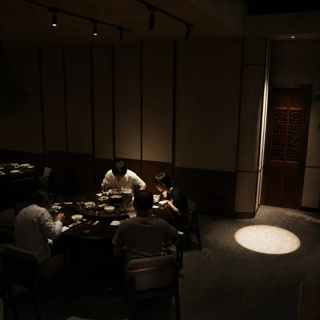
Dark tables, bright aisles and spill onto walls usually trace back to spacing, beam angle and aiming angle set in isolation rather than calculated together.
Dark tables next to bright aisles, and pools of light landing on the wall instead of the table, are among the most common complaints in hospitality lighting. In most cases the cause is the same: installation spacing, beam angle and aiming angle were each fixed by assumption rather than derived together. Three short calculations before the drawings are issued prevent almost all of it, and they cost far less than reworking a completed fit-out.
Step one: derive spacing from ceiling height
Measure the finished ceiling height and subtract the table height, typically 0.75 m. The result is the effective throw distance from the luminaire to the working surface, H.
Installation spacing ≤ 1.2 × H
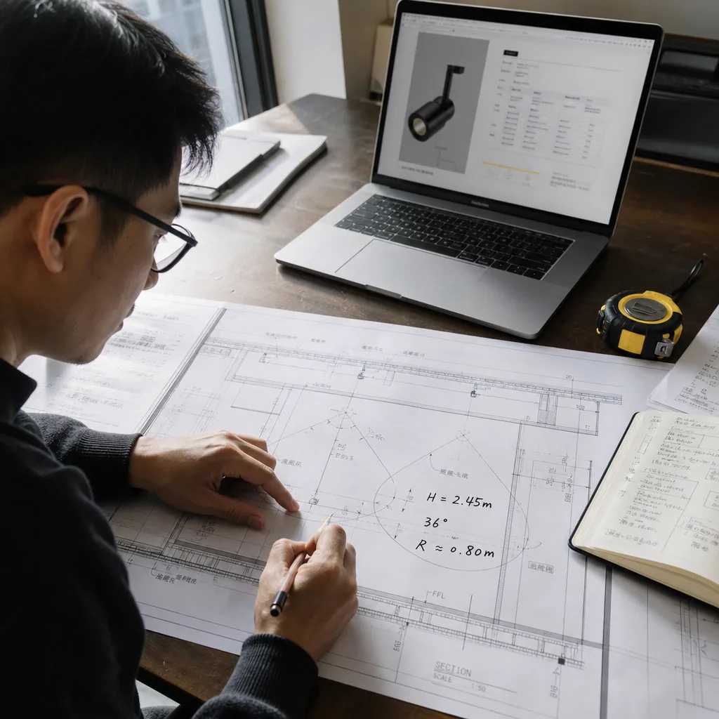
A finished height of 3.2 m with a 0.75 m table gives H = 2.45 m, so the maximum spacing is 2.45 × 1.2 ≈ 2.94 m.
Once spacing exceeds 1.2H, the circular pools from adjacent fittings no longer overlap sufficiently and a dim band forms on the table. That is the sensation of sitting in a particular seat and feeling you are in a shadowed corner.
The frequent error is applying a fixed 2.4 m grid module straight from a template without checking the real ceiling. A private room at 2.8 m finished height gives H = 2.05 m and a 2.46 m ceiling, so 2.4 m just works. At 2.6 m finished height, H = 1.85 m and the limit falls to 2.22 m, so the same 2.4 m grid is already over limit.
The discipline is simple: on every new project, measure the finished height, calculate H, calculate the spacing limit, and only then open the reflected ceiling plan.
Step two: use beam angle to find the lit radius
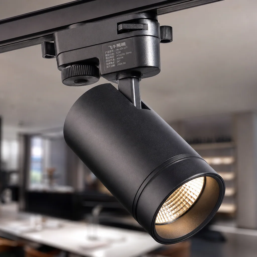
Check the beam angle on the luminaire datasheet, usually quoted as 24°, 36° or 60°. The beam angle describes how far the light opens out below the fitting. A smaller angle concentrates the light into a smaller circle; a larger angle spreads it into a wider, softer circle.
R = H × tan(beam angle / 2)
With H = 2.45 m and a 36° beam, R = 2.45 × tan(18°) ≈ 0.80 m, giving a pool roughly 1.6 m in diameter. That suits a 2.0 m four-seat table but spills over the chair backs on a 1.2 m round table.
| Beam angle | Typical application |
|---|---|
| 15°–24° | Accent lighting, artwork, display cases |
| 30°–45° | Single-table accent (standard dining tables) |
| 60° and above | Circulation fill, diffuse background light |
A common mistake is specifying a 15° narrow beam on a spotlight to chase high illuminance. The pool is only about 0.7 m across, leaving a bright disc in the centre of a four-seat table and dark edges where the food sits. A 36° or 45° beam is the better fit.
Step three: keep the aiming angle under 30°
On the section, draw the luminaire position and the target point at the centre of the table, then measure or calculate the aiming angle, the angle between the optical axis and vertical. A fitting pointing straight down has an aiming angle of 0°; the more it tilts, the larger the angle.
tan(aiming angle) = horizontal offset / H
With the fitting directly above the table, offset is zero and the pool lands dead centre. At an 0.8 m offset with H = 2.45 m, tan = 0.326 and the aiming angle is about 18°, which is safe.
The hard limit is 30°. Beyond it, two things happen at once. The pool stretches from a circle into a long ellipse, the effective area shrinks, edge scatter increases and light reaches the wall rather than the table. The source also rises into the seated diner's line of sight and produces direct glare. Glare is measured by UGR; values above 22 are uncomfortable, and dining spaces should aim for UGR ≤ 19.
Treat 0°–20° as preferred, 20°–30° as acceptable, and anything over 30° as a signal to re-plan the fixture positions or change the optic.
Common site errors and corrections
Track spotlight heads left hand-tight only hold insufficient torque. Air-conditioning airflow or a light knock drifts the angle by 5°–15°, and a month later the pool has moved from the table to the dado. Confirm each rotating joint to the specified torque with a torque screwdriver, typically 0.5–1.0 N·m, or use heads with a positive locking detent.
Plasterboard cut-outs that stray more than 20 mm from the setting-out plan shift the luminaire centre, push measured spacing outside the calculated range and degrade uniformity, the consistency of brightness across the table. Project the points onto the ceiling board with a laser before cutting and hold the error within ±10 mm. Where a cut-out is already too far out, compensate first with the fixture aiming angle and repair the opening in the finish only if necessary.
Installing a whole row of downlights vertically without any aiming is the third trap. Where the table is not directly below the fitting, as with wall banquettes or irregular layouts, the table centre is starved of light while the aisle ends up brighter than the table. Use adjustable downlights, usually ±30°, and confirm the aim table by table on site.
Acceptance criteria
Two figures carry the handover. Average illuminance on the table should be at least 300 lx, roughly the level at which fine print on a sheet of white paper is clearly legible. Table uniformity, defined as minimum illuminance divided by average, should be at least 0.6; below that, one corner differs from another by more than 40 percent and guests on the darker side feel the difference. Measure on a 0.5 m grid with an illuminance meter, ideally with a cosine-corrected head, and compute the ratio.
Selection and self-check list
Run through this before the drawings are issued.
- [ ] Finished ceiling height measured, H calculated
- [ ] Spacing ≤ 1.2H, drawing spacing checked
- [ ] Beam angle read from datasheet, radius R calculated, pool covers the target table
- [ ] Aiming angle noted for every position on the section, none over 30°
- [ ] Locking torque specified for adjustable fixture joints
- [ ] Cut-out positions laser-set, tolerance written into the method statement
- [ ] Acceptance plan includes meter readings against ≥ 300 lx and uniformity ≥ 0.6
For point-by-point layout review or photometric files to simulate a specific room, the Live With Matter application team can support the verification.